Piping Features Workflow
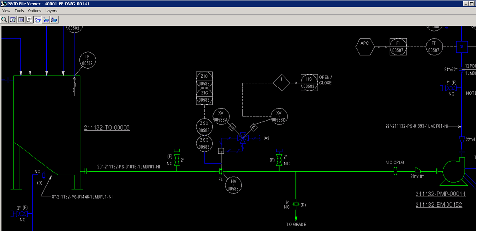
After all pipe runs have been correlated, they should appear green in the viewer. If they do not, it means there may be data or topology mismatch.
This example describes the steps for manual correlation of all inline components (along-leg features) one at a time.
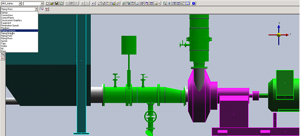
1. Set the selection filter to Piping Features
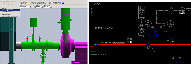
3. Under SmartPlant in the top ribbon, select Correlate with Design Basis.
Result: The system prompts the selected component to be correlated from P&ID view.
Result: The dialogue Compare with Design Basis opens.
4. Select the properties to update from design basis and click Update.
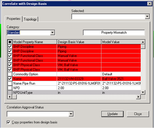
Note: The BHP Class Library attributes and item tag will be pushed from design basis to an S3D object.
5. Select the item as shown in the following screenshot and repeat steps 1-5 to manually correlate.
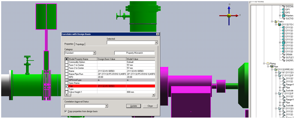
Repeat the manual correlation process for the remaining components of the pipe run.
6. Select the blind flange on the vertical 2” pipe run and correlate manually. Refer to Manual Correlation.
7. Select the properties to update from Design Basis and click Update.
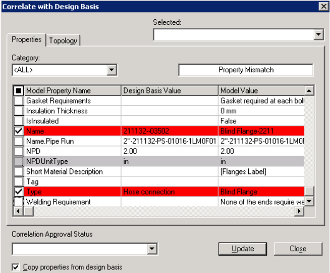
Note: Do not update the Type property unless that short code is defined in S3D piping specification. The P&ID Type values should match the short code in the S3D piping specification, which tells the system what type of part should be placed on the along leg feature.
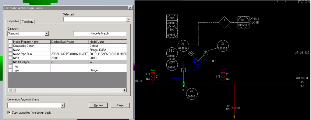
8. Correlate the coupling on the main 20-inch pipe run as shown in the following image:
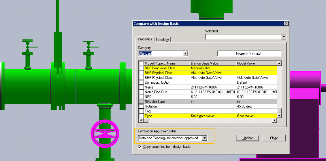
9. Correlate the valve on the 6-inch drain pipe run as shown in the following image.
As mentioned above since we do not knife gate valve short code in S3D specification therefore we will not update the Type property and approve this discrepancy by using the Correlation Approval Status.
The mismatch attributes that are approved show up in yellow and object will not appear green in the P&ID view, indicating that it is fully correlated.
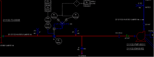
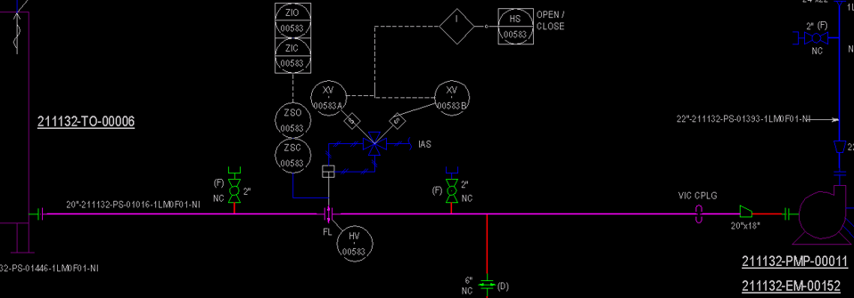
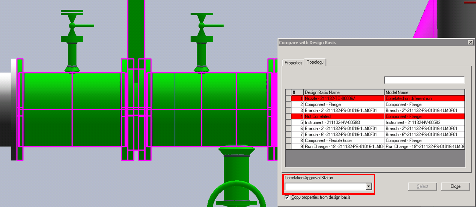
10. Now all pipe runs are correlated with main 20-inch pipe run, displayed in purple, which means there is topology mismatch.
a. Select the 20” pipe run in the S3D model
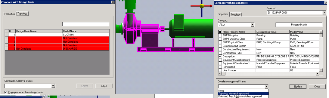
b. Expand the SmartPlant menu on the top ribbon and click Compare with Design Basis
c. Click the Topology tab
The items are displayed in red, which means the nozzle is not connected to the flange and the flange upstream is not connected to the HV valve. These two issues are causing topology mismatch.
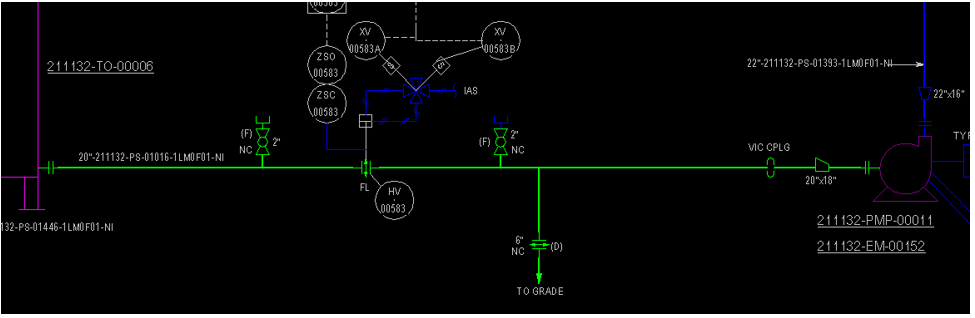
In this example, the Correlation Approval Status is set to Topology Mismatch Approved.
Result: The whole pipeline is highlighted green, which means it is fully correlated.
The two pieces of equipment are displayed in purple, which means they have topology mismatch.
a. Select the pump in the S3D model
b. Expand the SmartPlan menu on the top ribbon and click Compare with Design Basis
c. Click the Topology tab
Since only the suction nozzle is connected, while the other nozzles are disconnected, there is topology mismatch. In this example, the Correlation Approval Status is set to Topology Mismatch Approved.
Result: All P&ID objects are highlighted green, which means all are fully correlated.